- For stability, use a NPO types for C2 & C4.
- Resistance tolerance for R1 should be 1 or 2%.
- Frequency range is the usual 87-109Mhz on the FM dial.
- The coil is made from 22 ga 'hookup' wire, like the solid Bell phone wire. Leave the insulation on.
- The LED is the 'High Brightness' type for maximum illumination.
Showing posts with label fm transmiter. Show all posts
Saturday, March 12, 2011
1.5 Volt Tracking Transmitter
Labels:
fm transmiter
Saturday, August 28, 2010
BH1417 Stereo PLL FM Transmitter
| 1x BH1417 - Stereo PLL Transmitter IC (Case SOP22) 1x 7.68 MHz Crystal 1x MPSA13 - NPN Darlington Transistor 1x 2.5 Turns Variable Coil 1x MV2109 - Varicap Diode 1x 4-DIP Switch ANT - 30 cm of copper wire 1x 22K Resistor 7x 10K Resistor 1x 5.1K Resistor 2x 3.3K Resistor 1x 100 Ohm Resistor | 1x 100uF Capacitor 3x 10uF Capacitor 2x 1uF Capacitor 1x 47nF Capacitor 3x 2.2nF Capacitor 1x 1nF Capacitor 1x 330pF Capacitor 2x 150pF Capacitor 1x 33pF Capacitor 2x 27pF Capacitor 1x 22pF Capacitor 2x 10pF Capacitor |
| Technical Specifications: | |
|
About BH1417 Stereo PLL FM Transmitter
This is the latest BH1417 FM Transmitter design from RHOM that includes a lot of features in one small package. It comes with pre-emphasis, limiter so that the music can be transmitted at the same audio level, stereo encoder for stereo transmission, low pass filter that blocks any audio signals above 15KHz to prevent any RF interference, PLL circuit that provides rock solid frequency transmission (no more frequency drift), FM oscillator and RF output buffer.There are 14 possible transmission frequencies with 200KHz increments that users can select with a 4-DIP switch. Lower band frequencies start from 88.7 up to 89.9 MHz, and upper band frequencies start from 107.7 up to 108.9 MHz.
BH1417 can be supplied with 4 - 6 voltage and consumes only around 30mA, providing 20mW output RF power. BH1417 provides 40dB channel separation which is pretty good, although older BA1404 FM Transmitter chip provides slightly better 45dB channel separation.
BH1417 is only available in SOP22 IC case so this may be an inconvenience for some folks. On the other hand, because the chip is smaller than regular DIP-based ICs it is possible to fit the entire transmitter on a small PCB.
The bad news is that BH1417 requires 7.6MHz crystal oscillator, which is very hard to find. The good news is that you can use 7.68 MHz crystal instead, which is easier to find. In fact our BH1417 transmitter prototype (schematic shown above) uses 7.68 MHz crystal. This has absolutely no effect on stereo encoding process, we have tested it and stereo sound is crystal clear. The transmitted frequency on the other hand will be shifted up by exactly 1MHz (example: 88.1 MHz to 89.1 MHz) which is perfectly fine. The frequencies that are used in this project have been adjusted by 1MHz already so no additional conversion is necessary.
BH1417 chip may also be used a stand alone stereo encoder. The advantage of that is that you have full freedom of using a transmitter & amplifier of your choice. You will still have a pre-emphasis, limiter, stereo encoder and low pass filter in one small package because very few external components are required for these blocks. PIN 5 is MPX output that can be directly connected to an external FM transmitter through a 10uF cap.
BH1417 Block Diagram
Main blocks of BH1417 chip are; pre-emphasis, (audio level) limiter, stereo encoder (MPX), PLL circuit, oscillator and RF buffer.
Frequency selection is very straight forward. Simply select transmission frequency at which you would like to transmit, set the combination for 4-DIP switch and BH1417 will immediately tune to that frequency. If you can't hear the transmitted audio signal on your FM receiver then re-adjust 2.5 turn variable coil until you can hear the signal. If you have a laboratory power supply you may try to vary the voltage supply from 4 to 6V. While doing that BH1417 will automatically vary the voltage for MV2109 varicap diode making sure that there's no frequency drift.
| S4 | S3 | S2 | S1 | Frequency |
| 1 | 1 | 1 | 1 | 88.7 MHz |
| 1 | 1 | 1 | 0 | 88.9 MHz |
| 1 | 1 | 0 | 1 | 89.1 MHz |
| 1 | 1 | 0 | 0 | 89.3 MHz |
| 1 | 0 | 1 | 1 | 89.5 MHz |
| 1 | 0 | 1 | 0 | 89.7 MHz |
| 1 | 0 | 0 | 1 | 89.9 MHz |
| 1 = ON, 0 = OFF | ||||
Frequently Asked Questions
This is list of answers to questions that I have received through an e-mail so far. If you should have any other questions please don't hesitate to e-mail them to me.
What is the range of BH1417 Stereo FM Transmitter?This is list of answers to questions that I have received through an e-mail so far. If you should have any other questions please don't hesitate to e-mail them to me.
Range of the transmitter depends on many factors.
a) Length and type of the antenna (the longer the better, copper will radiate radio waves better than aluminum)
b) Supplied voltage (6V Max power output)
c) Weather conditions (clear skies & no humid, greater distance)
d) Elevation above the ground (the higher the better)
e) Line of sight (no buildings or trees, greater distance)
f) Whether external amplifier is used
I would like to be able to transmit the music to greater distances. Can you provide any suggestions on how to modify the circuit?
You can connect an external amplifier based on the common 2N3866 / 2N4427 RF transistors. Please keep in mind that it is illegal to operate higher power transmitters in most of the countries without the proper license.
Labels:
fm transmiter
2 km FM transmitter
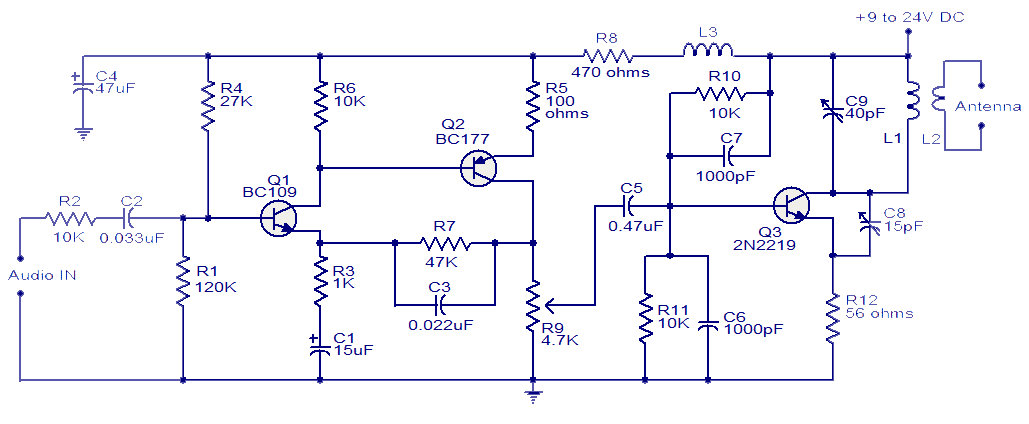
With a matching antenna, the FM transmitter circuit shown here can transmit signals up to a range of 2 kilo meters. The transistor Q1 and Q2 forms a classic high sensitive preamplifier stage. The audio signal to be transmitted is coupled to the base of Q1 through capacitor C2. R1, R3, R4, R6, R5 and R9 are the biasing resistors for the preamplifier stage comprising of Q1 and Q2. Transistor Q3 performs the collective job of oscillator, mixer and final power amplifier. C9 and L1 forms the tank circuit which is essential for creating oscillations. Inductor L2 couples the FM signal to the antenna.
Circuit diagram.
Notes.
- Assemble the circuit on a good quality PCB.
- The circuit can be powered from anything between 9 to 24V DC.
- Inductor L3 can be a VK220J type RFC.
- For L1 make 3 turns of 1mm enamelled copper wire on a 10mm diameter plastic former. On the same core make 2 turns of 1 mm enamelled copper wire close to L3 and that will be L2.
- Frequency can be adjusted by varying C9.
- R9 can be used to adjust the gain.
- For optimum performance, value of C8 must be also adjusted.
- Using a battery for powering the circuit will reduce noise.
Labels:
fm transmiter
Monday, August 16, 2010
BH1417 Stereo PLL FM Transmitter
This is the latest BH1417 FM Transmitter design from RHOM that includes a lot of features in one small package. It comes with pre-emphasis, limiter so that the music can be transmitted at the same audio level, stereo encoder for stereo transmission, low pass filter that blocks any audio signals above 15KHz to prevent any RF interference, PLL circuit that provides rock solid frequency transmission (no more frequency drift), FM oscillator and RF output buffer.
There are 14 possible transmission frequencies with 200KHz increments that users can select with a 4-DIP switch. Lower band frequencies start from 88.7 up to 89.9 MHz, and upper band frequencies start from 107.7 up to 108.9 MHz.
BH1417 can be supplied with 4 - 6 voltage and consumes only around 30mA, providing 20mW output RF power. BH1417 provides 40dB channel separation which is pretty good, although older BA1404 FM Transmitter chip provides slightly better 45dB channel separation.
BH1417 is only available in SOP22 IC case so this may be an inconvenience for some folks. On the other hand, because the chip is smaller than regular DIP-based ICs it is possible to fit the entire transmitter on a small PCB.
The bad news is that BH1417 requires 7.6MHz crystal oscillator, which is very hard to find. The good news is that you can use 7.68 MHz crystal instead, which is easier to find. In fact our BH1417 transmitter prototype (schematic shown above) uses 7.68 MHz crystal. This has absolutely no effect on stereo encoding process, we have tested it and stereo sound is crystal clear. The transmitted frequency on the other hand will be shifted up by exactly 1MHz (example: 88.1 MHz to 89.1 MHz) which is perfectly fine. The frequencies that are used in this project have been adjusted by 1MHz already so no additional conversion is necessary.
BH1417 chip may also be used a stand alone stereo encoder. The advantage of that is that you have full freedom of using a transmitter & amplifier of your choice. You will still have a pre-emphasis, limiter, stereo encoder and low pass filter in one small package because very few external components are required for these blocks. PIN 5 is MPX output that can be directly connected to an external FM transmitter through a 10uF cap.

BH1417 Block Diagram
Parts:
1x BH1417 - Stereo PLL Transmitter IC (Case SOP22)
1x 7.68 MHz Crystal
1x MPSA13 - NPN Darlington Transistor
1x 2.5 Turns Variable Coil
1x MV2109 - Varicap Diode
1x 4-DIP Switch
ANT - 30 cm of copper wire
1x 22K Resistor
7x 10K Resistor
1x 5.1K Resistor
2x 3.3K Resistor
1x 100 Ohm Resistor 1x 100uF Capacitor
3x 10uF Capacitor
2x 1uF Capacitor
1x 47nF Capacitor
3x 2.2nF Capacitor
1x 1nF Capacitor
1x 330pF Capacitor
2x 150pF Capacitor
1x 33pF Capacitor
2x 27pF Capacitor
1x 22pF Capacitor
2x 10pF Capacitor1x BH1417 - Stereo PLL Transmitter IC (Case SOP22)
1x 7.68 MHz Crystal
1x MPSA13 - NPN Darlington Transistor
1x 2.5 Turns Variable Coil
1x MV2109 - Varicap Diode
1x 4-DIP Switch
ANT - 30 cm of copper wire
1x 22K Resistor
7x 10K Resistor
1x 5.1K Resistor
2x 3.3K Resistor
1x 100 Ohm Resistor 1x 100uF Capacitor
3x 10uF Capacitor
2x 1uF Capacitor
1x 47nF Capacitor
3x 2.2nF Capacitor
1x 1nF Capacitor
1x 330pF Capacitor
2x 150pF Capacitor
1x 33pF Capacitor
2x 27pF Capacitor
1x 22pF Capacitor
sumber: http://electronics-diy.com
Labels:
fm transmiter
BA1404 HI-FI Stereo FM Transmitter
Whether you want to create your own radio station, transmit the music around the house, or simply create a wireless link between your iPod and a receiver in your car, this transmitter will let you do these things easily. With BA1404 HI-FI Stereo transmitter you will be able to transmit MP3 music from your iPod, computer, discman, walkman, TV / SAT receiver, and many other audio sources.
The above FM transmitter design is a result of many hours of testing and tweaking. The goal was simple; to test many existing BA1404 transmitter designs, compare their performance, identify weaknesses and come up with a new BA1404 transmitter design that improves sound quality, has very good frequency stability, maximizes transmitter's range, and is fairly simple for everyone to build. We are happy to announce that this goal and expectations have been met and even exceeded.
The transmitter can work from a single 1.5V cell battery and provide excellent crystal clear stereo sound. It can also be supplied from two 1.5V battery cells to provide the maximum range.
Labels:
fm transmiter
Subscribe to:
Posts (Atom)